


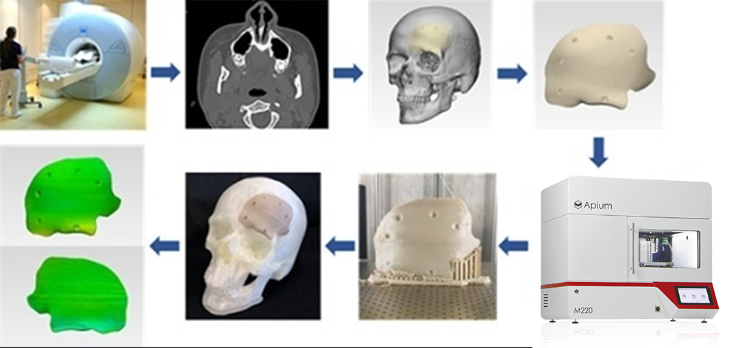
With the development of personalized medicine, patient-specific implants (PSIs) are increasingly used in craniofacial reconstruction surgery. Polyether ether ketone (PEEK), a new biocompatible material with excellent mechanical properties and no magnetic resonance imaging artifacts, is widely used in vertebral fusion surgery. In recent years, PEEK materials have also begun to be used in the fabrication of customized cranial implants. Fused deposition manufacturing (FDF)-based 3D printing technology has made it possible to achieve individualized designs for PEEK implants compared to traditional milling processes, and is particularly suitable for small-volume custom production. However, the glass transition temperature of PEEK polymers is as high as 143°C, which poses a great challenge for the temperature control of the FFF printing process. During the printing of medical-grade PEEK implants, it is difficult to achieve a homogeneous material arrangement, and amorphous areas and residual internal stresses often occur, resulting in inhomogeneous mechanical properties of the printed implants. In addition, the complex anatomical structure also increases the difficulty of optimizing the FFF process parameters.
Several medical and academic institutions from Switzerland and the Netherlands have conducted a study on 3D printed customized PEEK implants for craniofacial reconstruction applications. These participating institutions include medical institutions such as the University Hospital of Basel, Switzerland, the University of Basel, Switzerland, and the Cantonal Hospital of Basel, Switzerland, as well as academic research institutions such as the University of Amsterdam, the Netherlands. Conducting research on the optimization of PEEK printing parameters and evaluating the effectiveness of its clinical application in craniofacial reconstructive surgery is significant in advancing the clinical translation of this technology.
▍Materials and methods
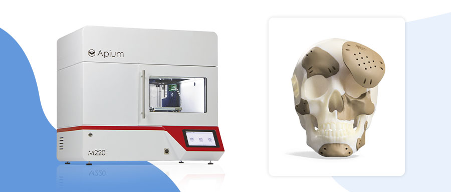
1、3D printing equipment:Parametric specifications of the Apium M220 3D printer (Table 1).

2、Processing material: Parametric indicators for PEEK print filament.
The printing material used for the study was a 1.75 mm medical grade PEEK printing filament (VESTAKEEP® i4 G, Evonik Industries AG). The PEEK material, which contains no reinforcing fillers, is a natural-colored, high-viscosity thermoplastic polymer with a density of 1.30 g/cm³ and a melting temperature of 380°C. This type of PEEK material is specifically designed for use in the manufacture of long-term implantable medical devices and has excellent biocompatibility.
3、METHODS: A printed parametric test program was designed based on Taguchi's DOE method (Table 2, Table 3).
In order to optimize the printing parameters of PEEK implants, a printing test protocol was designed using Taguchi's design of experiments method. Four printing parameters were selected: layer thickness (150/200/250 μm), fill rate (60%/70%/80%), number of shells (1/2/3), and fill pattern (linear/rectangular/triangular), and three levels were set for each parameter (Table 2). Based on the L9 (34) orthogonal array, nine sets of parameter combinations were obtained (Table 3), and the test samples were printed separately. Sample dimensions were measured using a digital micrometer (accuracy ±0.001mm), with 12 points in each direction for each sample, and each point was repeated 3 times to take the average value. The percentage change in dimensions was calculated according to equation (1):
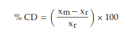 (1)
(1)
Where xm is the measured mean value and xr is the CAD design value of 20 mm.
Equation (2) was used to calculate the root mean square and to evaluate the overall 3D bias of the samples:
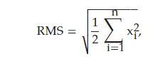 (2)
(2)
Where xi and yi are the coordinates of the corresponding points and n is the number of pairs of points. smaller RMS values indicate higher accuracy of the sample size.
One-way ANOVA and signal-to-noise ratio analyses were performed to identify the optimal combination of parameters that minimized CD and RMS to improve the printing accuracy of PEEK implants.

Table 2: FFF PEEK 3D printing process parameters and levels selected for the experiment.

Table 3: Experimentally generated orthogonal arrays for Taguchi L9 (34).
4、Preparation of samples: Printing of parameter combination samples and recording of dimensional accuracy change data.
A total of nine test samples were prepared based on the nine combinations of printing parameters generated from the L9 orthogonal array (Table 3). To reduce the effect of test errors, each sample was prepared separately in the center of the printer build platform. The samples were cubes with a side length of 20 mm, designed using CAD software and exported as STL files (Figure. 1).
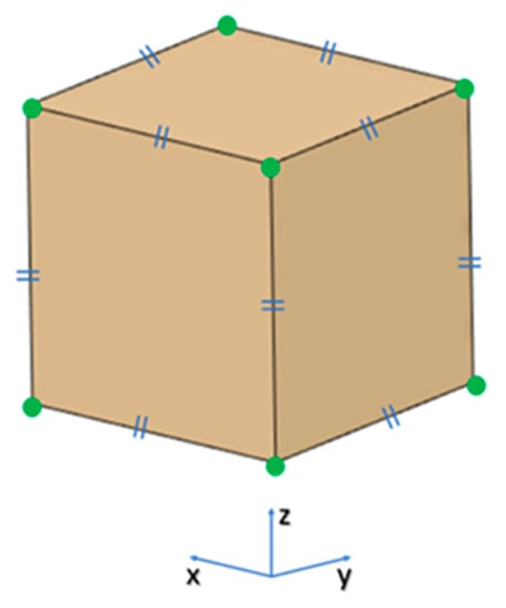
Figure.1. Projected view of the test object showing landmarks: the green dots represent the measured landmarks and the blue symbols represent the equal dimensions of the test object in the x, y and z axes (20 mm).
After printing, 12 linear dimensions of each sample in the x, y, and z axes were measured using digital electronic vernier calipers (Sheffield, accuracy ±0.001 mm), and each dimension was repeated three times to take the average value. The percentage change in dimensions of each sample in different directions was calculated according to equation (1).
The data on the dimensional accuracy of the samples prepared under these nine sets of different parameters provide a detailed quantitative basis for subsequent optimization experiments. In the following, statistical methods such as one-way ANOVA will be applied to find out the optimal parameter combination that leads to the least dimensional change.
▍Results and analysis
1、Print parameter optimization results
The optimal combination of printing parameters to minimize the dimensional variation was determined by ANOVA and S/N analysis as A2B2C2D2, i.e., layer thickness of 150 μm, fill rate of 80%, number of shells of 2 layers, and linear filling (Table 4 and Figure. 2). This set of parameters helps to improve the dimensional accuracy by reducing the layer thickness and fill line while ensuring adequate filling.
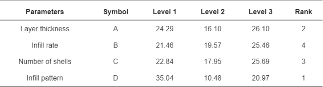
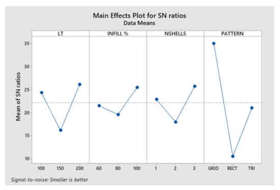
Figure.2 .Plot of the main effect of signal-to-noise ratio (S/N). lt, layer thickness; INFILL%, fill rate; NSHELLS, number of shells; PATTERN, fill pattern.
2、Evaluation results of different kinds of PSI accuracy
The study evaluated the printing accuracy of PEEK cranial implant samples with two different anatomical structures. Group 1 showed a greater error with a mean deviation of 0.731 mm and a median deviation of 0.704 mm (Figure. 3), while Group 2 showed a smaller error with a mean deviation of 0.238 mm and a median deviation of 0.241 mm (Figure. 7). The results of calculating the root mean square also showed that the error of group 1 could be up to 0.790 mm, while group 2 was only 0.241 mm (Table 5).
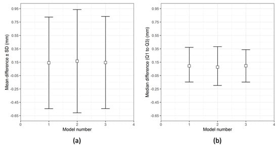
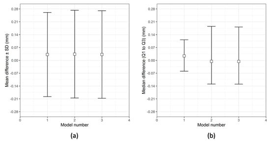
Figure.4: Descriptive data distribution of Group 2 PSIs illustrating differences between planned and FFF 3D printed PEEK PSIs (PSI Models 1-3). (a) Mean difference ± SD (mm) and (b) Median difference (Q1 to Q3) (mm). Comparative analysis of PEEK PSIs in group 1 showed that the mean difference (± SD) was 0.731 ± 0.051 mm and the median difference (Q1 to Q3) was 0.704 (0.699-0.790) mm. on the other hand, comparative analysis of PSIs in group 2 showed that the mean difference (± SD) was 0.238 ± 0.006 mm and the median difference (Q1 to Q3) was 0.241 (0.231-0.006) mm. 0.241 (0.232-0.242) mm.
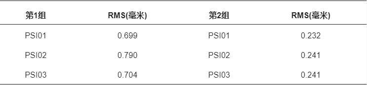
Table 5. Quantitative assessment of the root mean square value (mm) of dimensional accuracy of FFF 3D printed PEEK patient-specific implants (PSI).
3、Reasons for the difference in accuracy between the two PSIs
The PSI structure of group 1 is more complex and the surface span is larger, so it is more difficult to print and the error is larger. In addition, the uneven crystallization during the printing process of group 1 resulted in darker color areas (Figure. 5), which corresponded to the error areas; while group 2 had uniform colors.

Figure.5. Group 1 PSI showing signs of slight discoloration (dark brown areas).
4、Process Challenges
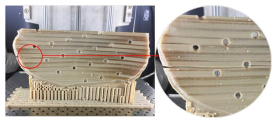
The results show that the position of the support structure as well as the print orientation of the PEEK affects the surface quality (Figure. 6); faulting may also occur when printing large and complex implants (Figure. 7). This requires optimization of thermal management and reduction of internal stresses to improve print quality.
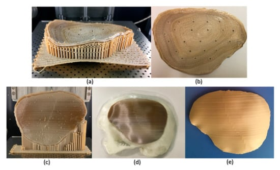
Figure. 6. Schematic representation of the FFF PEEK 3D printing problem for cranial implants with different orientations. (a) horizontally printed cranial implant showing raft shedding/warping effect (in situ); (b) horizontally printed cranial implant showing rough inner surface; (c) vertically printed cranial implant showing varying degrees of crystallinity (in situ); (d) 3D-printed biomodel of the skull versus vertically printed implant after removal of the support structure; and (e) vertically printed cranial implant after annealing showing no discoloration .
▍Advantages of printing PEEK material in craniofacial reconstructive surgery with FFF technology
Compared with traditional manufacturing techniques, FFF technology can custom design and fabricate personalized PEEK implants, enabling cranial reconstruction surgery to achieve precision medicine in the true sense of the word. The results of this study showed that using optimized parameter settings (Fig. 5), the printing accuracy of group 2 PEEK implants could reach 0.241 mm (Table 5), which meets the clinical requirements.
▍Problems and direction of optimization
For Group 1 large PEEK implants with complex curvature changes, the printing accuracy was only 0.790 mm (Table 5), which could not meet the clinical requirements. The main reason for this was poor thermal management, which resulted in non-uniform PEEK material arrangement (Figure 9). This requires optimization of thermal management strategies to reduce the generation of residual stresses.
▍Application Prospects
With the continuous optimization of FFF technology, personalized implant printing based on PEEK materials will certainly advance cranial reconstruction surgery towards precision medicine. In the future, new PEEK materials can be developed to optimize the printing path and achieve precise customized printing of complex anatomical structures. This technology has a bright future.
▍Apium M220
Pressing the "Accelerator Button" for Precision Medicine
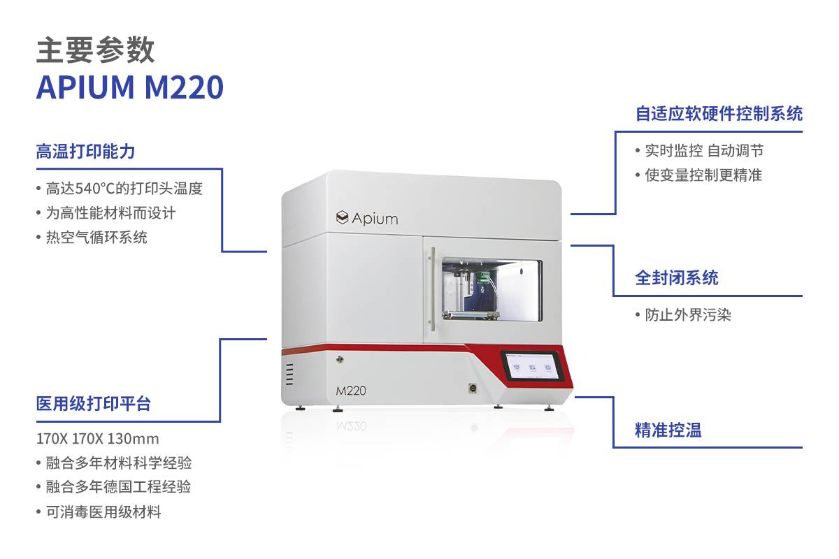
An Apium M220 3D printer was used in the study to investigate the effect of optimizing non-thermal parameters on the print quality of PEEK implants. The results show that using optimized parameters it is possible to achieve clinically acceptable precision for PEEK implants with specific anatomical structures. However, the printing of large and complex implants still faces thermal management challenges. technical advantages such as the closed-cycle temperature control system of the Apium M220 give it great potential for print quality improvement. Further research can be carried out in the future to optimize the thermal parameter settings and solve the temperature stability problem during the printing process. There is also great potential for material formulation and print path optimization.
Overall, FFF technology printing PEEK personalized implants has a broad clinical application prospects, will certainly promote the development of cranial reconstruction surgery to the development of precision medicine, for precision medicine to press the "accelerator button".
Bibliography:Quality Characteristics and Clinical Relevance of In-House 3D-Printed Customized Polyetheretherketone (PEEK) Implants for Craniofacial Reconstruction.DOI:10.3390/jcm9092818
 Home
Home Telephone
 Message